Undercarriage Display Unit (UCDU) Test Jig for Fighter Aircraft

Development Background

The Need for UCDU Testing in Fighter Aircraft

For fighter jets, the landing gear system, and its corresponding display unit are critical for safe takeoffs and landings. The Undercarriage Display Unit informs the pilot of the landing gear’s status, including whether it is extended or retracted. Any failure or inaccuracy in this system can lead to disastrous consequences, particularly during high-speed landings.

The UCDU Test Jig was developed to simulate conditions the landing gear may encounter, allowing maintenance teams to test and validate the UCDU’s responses. Before this test jig, maintenance personnel faced challenges in accurately simulating all potential landing gear scenarios, making it difficult to ensure that the UCDU was operating at peak efficiency. The need for a comprehensive, automated testing solution that could replicate real-world conditions was evident.

The UCDU Test Jig was designed to offer a complete, versatile testing platform, incorporating features for dynamic simulation of the undercarriage system. These features enable maintenance engineers to test multiple UCDU functions, ensuring all switches and indicators work properly.

Structural and Electrical Components

The UCDU Test Jig is built around a robust and durable mechanical enclosure, housing all essential equipment, including a built-in voltmeter and ammeter for precise voltage and current measurements during tests. The system is designed to operate on 230V, 50Hz single-phase AC power and provides a regulated 28V DC supply for testing the UCDU under realistic operating conditions. The rear panel includes an MCB (Miniature Circuit Breaker) with short-circuit and over-current protection for additional safety during operations.

Operations and Workflow

Testing Process

The UCDU Test Jig enables streamlined testing procedures for the aircraft’s UCDU system. The testing workflow can be divided into the following stages:

  1. Power-Up: The test jig is powered through a 230V AC input, supplying regulated 28V DC to the UCDU for realistic simulations.
  2. Undercarriage Status Simulation: The 15 functional switches on the test jig are used to simulate different landing gear statuses, which are critical to ensuring the UCDU accurately reflects the real-world state of the undercarriage.
  3. Lamp Testing: The 13 toggle switches and two pushbutton switches verify the indicator lamps within the cockpit, ensuring they light up when the corresponding landing gear statuses are triggered.
  4. Self-Test and Indicator Checks: The Self-Test pushbutton ensures the test jig functions correctly before starting the UCDU test. This step helps avoid false results due to test equipment malfunction.
  5. Voltage and Brightness Testing: The variable voltage toggle switch and rotating knob allow for testing the brightness of the UCDU’s LEDs, simulating conditions with different cockpit lighting environments.
  6. Signal Integrity: Using the duty cycle measurement sockets, the test jig verifies the integrity of pulse-width modulated signals for accurate undercarriage status reporting.
  7. Completion: Once all tests are complete, the test jig logs and reports the results, ensuring the UCDU is fit for deployment in the fighter aircraft.

Safety Features and Protections

The UCDU Test Jig is built with short circuit protection and over-current limits on all inputs and outputs, safeguarding both the test jig and the UCDU from damage. The rear panel MCB provides additional protection against electrical faults, while an indicator buzzer alerts operators in case of signal inconsistencies during testing.

Its sophisticated design and comprehensive testing capabilities ensure an aircraft’s UCDU performs reliably. With precise simulation and testing of undercarriage statuses, the system guarantees that pilots receive accurate and timely feedback during critical landing and takeoff operations. This tool has increased the efficiency of the UCDU maintenance process and enhanced the overall safety and reliability of the fighter aircraft.

Precision in Aircraft Structural Testing: Solutions for Data Acquisition Systems in Fighter Aircraft

Structural testing is the backbone of aircraft development, ensuring that every part of an aircraft can withstand the stresses and strains encountered during operation. Fighter aircraft are subjected to extreme conditions, and structural integrity is paramount to perform under combat conditions. Mission outcomes depend on rigorous testing protocols that simulate real-world scenarios.

The SCTF evaluates how different parts of the aircraft structure interact under differing weapons loads, speeds, and environmental conditions. It helps engineers understand the aircraft behavior, enabling them to refine design and enhance performance. The DAS provides the data needed to make decisions for aircraft design.

Key Features of the Data Acquisition System

The DAS used in the SCTF for fighter aircraft is a comprehensive solution that integrates multiple advanced features, making it one of the most sophisticated systems of its kind. Below are the key components and functionalities of the system:

  1. High-Speed Data Acquisition: The system supports over 2000 strain channels, each capable of sampling data at rates exceeding 50,000 samples per second. This high-speed data acquisition capability is crucial for capturing detailed information during structural tests, especially when dealing with high-frequency events or transient phenomena. The ability to collect data at such high rates ensures that no critical information is missed, allowing for a thorough analysis of the aircraft’s behavior under test conditions.
  2. Strain Measurement and Fatigue Analysis: Strain measurement involves measuring the deformation of the aircraft’s structure when subjected to external forces. The DAS’ structure-mounted transducers accurately measure strain across different aircraft parts. This data is then used for fatigue analysis, which predicts the lifespan of aircraft components by evaluating how they respond to repeated stress over time. Fatigue analysis is essential for identifying potential failure points and ensuring that aircraft operate safely throughout its intended service life.
  3. Health Usage and Monitoring System (HUMS): The DAS Health Usage and Monitoring System (HUMS) continuously monitors the health and usage of fighter aircraft. HUMS tracks various parameters, such as vibration levels, temperature, and load cycles, to assess the condition of the aircraft’s components, providing real-time insights into the aircraft’s health. HUMS enables predictive maintenance, reducing downtime and improving operational efficiency.
  4. High-Voltage and Digital Input/Output Channels: The system includes over 100 high-voltage channels and approximately 50 digital input/output (DIO) channels for handshaking and servo control. These channels are used for precise control and measurement during tests, ensuring test environments can be replicated and controlled. The high-voltage channels are important for tests involving electrical components, while the DIO channels facilitate communication between different parts of the system, enabling coordinated control and data collection.
  5. Signal Conditioning with Wideband Amplifiers: Accurate data acquisition requires careful signal conditioning to ensure that the signals from the transducers are not distorted by noise or other interference. The DAS uses wideband amplifiers for signal conditioning, which amplifies the signals while preserving their integrity. This ensures that the data collected is high-quality for reliable analysis.
  6. Comprehensive Software for Data Processing and Analysis: The DAS is complemented by specialized software that handles high-speed data acquisition, control, signal processing, analysis, and report generation. This software manages large volumes of data generated during tests, processing it in real-time to provide immediate feedback. The software does more than just collect data; it features advanced algorithms for signal processing and analysis, allowing engineers to derive meaningful insights from the information. The software generates detailed reports of the test results, providing a clear record of the aircraft’s performance.

Applications in the Development for the Next Generation of Fighter Aircraft

Fighter aircraft are built for specific usages. Some such aircraft are air superiority, multirole, interceptors, ground attack, carrier-based, stealth, training, and reconnaissance missions. Given their operational requirements, the aircraft must be exceptionally robust, reliable, and capable of performing in combat scenarios.

  1. Structural Coupling Tests: One of the primary applications of the DAS in the development of fighter aircraft is structural coupling tests. These tests evaluate how different parts of the aircraft’s structure interact when subjected to various loads and environmental conditions. By analyzing the data collected during these tests, engineers can identify potential weaknesses in the structure and make necessary adjustments to improve the aircraft’s performance. The high-speed data acquisition capabilities capture detailed information on how the structure behaves under dynamic conditions.
  2. Fatigue Testing: Fighter aircraft are subject to repeated stress during their operational life. Fatigue testing involves subjecting the aircraft’s structure to repeated loads to simulate the conditions it will encounter during service. The DAS measures the resulting strain and uses this data to predict the lifespan of the aircraft’s components. This information is vital for ensuring that fighter aircraft can operate safely over its intended lifespan, reducing the risk of in-service failures.
  3. Health Monitoring and Predictive Maintenance: By tracking key health indicators of fighter aircraft during testing and operational phases, HUMS provides real-time insights into the condition of the aircraft’s components. This enables predictive maintenance, where potential issues are identified and addressed before they lead to problems. For fighter aircraft, which are expected to operate in demanding environments, predictive maintenance is essential for maximizing availability and minimizing downtime.

The Case for Advanced Data Acquisition Systems

The benefits of the DAS extend far beyond the initial costs, offering substantial returns in terms of safety, reliability, and performance.

  1. Enhancing Aircraft Safety and Reliability: Pilot safety is the foremost priority for any air force, and advanced DAS systems provide detailed insights into the structural behavior of the aircraft. These systems enable engineers to design more robust and reliable structures, reducing the risk of in-service failures.
  2. Improving Operational Efficiency: By identifying potential issues before they lead to failures, predictive maintenance reduces the need for unscheduled repairs and minimizes aircraft-on-ground (AOG) incidents. This improves the availability of the aircraft and reduces maintenance costs over the aircraft’s operational life.
  3. Supporting Continuous Improvement: Engineers use data collected by the DAS to analyze the results of structural tests and fatigue analysis for design improvement and implement changes to improve aircraft performance. This continuous improvement ensures that the fighter aircraft meets modern warfare standards.

For fighter aircraft to perform in combat scenarios, the DAS enables safety, reliability, and performance. Aircraft performance pushes the boundaries of what is possible, and advanced systems like the DAS play an increasingly important role in shaping the future of aircraft design. By integrating high-speed data acquisition, strain measurement, fatigue analysis, and health usage monitoring, this system provides an end-to-end solution that supports the entire lifecycle of the aircraft, from development to operational deployment.

Delivering Mission-Critical Defense Equipment Reliability with the Pinaka G-Meter

At Pinaka Aerospace Solutions, we’re known for our commitment to indigenization and innovation, and we have developed a solution to address this challenge: the G-Meter. This advanced device monitors and records shock, vibration, and environmental conditions experienced by mission-critical equipment, ensuring that these systems remain operationally effective and reliable throughout their lifecycle.

The Importance of Environmental Monitoring

Before examining the specifics of the G-Meter, it is important to understand the broader context in which such a device operates. Mission-critical equipment in the aerospace and defense sectors is subjected to harsh conditions, whether during a high-speed flight, a rough landing, or transportation over uneven terrain. This stress can manifest as mechanical shock, sustained vibration, or exposure to extreme temperatures, and lead to wear and tear or even outright failure if not properly managed.

Environmental monitoring is essential to maintain such equipment. By accurately tracking the conditions under which a system operates, maintenance teams can identify potential issues before they escalate, schedule preventative maintenance, and extend the operational life of the equipment. In essence, effective environmental monitoring enhances the reliability and cost-effectiveness of mission-critical systems.

The Pinaka G-Meter

Pinaka’s G-Meter is specifically designed to address the rigorous demands of mission-critical equipment. This device is the culmination of extensive research and development, tailored to meet the requirements of defense systems. The G-Meter is a compact, self-contained unit that offers a range of advanced features, making it an indispensable tool for military organizations looking for the highest standards of equipment reliability.

Key Features of the G-Meter

  1. High-Impact Event Recording: One of the standout features of the G-Meter is its ability to record impact events of up to 16G, where equipment may be exposed to sudden and severe shocks—such as during a hard landing or an explosion—this capability is critical. The G-Meter captures the magnitude of these impacts and their direction and provides a comprehensive view of the forces at play. Users can set thresholds, ensuring that the G-Meter records the time, location, and shock levels for those impact events above the defined thresholds. This saves both battery and memory.
  2. Multi-Axis Monitoring: The G-Meter records data along the X, Y, and Z axes, offering a complete picture of the stresses experienced by the equipment. This is especially important in operating environments where forces can act in multiple directions simultaneously. By monitoring each axis individually, the G-Meter ensures no detail is overlooked, enabling more accurate assessments of equipment condition.
  3. Temperature Recording: The Pinaka G-Meter tracks temperature over time. This is a fundamental feature for equipment that operates in environments with fluctuating temperatures since thermal stress can adversely impact system performance and longevity. The G-Meter helps maintenance teams understand how thermal conditions contribute to overall equipment stress.
  4. Self-Contained Design: As a self-contained unit, free of external cables and wires, its design choice offers several advantages. First, it reduces the risk of cable damage, which could compromise the integrity of the data collected. Second, it simplifies installation and deployment for easy integration of the G-Meter into an array of systems. Finally, the self-contained nature of the device enhances its durability, as fewer external components could be damaged or disconnected.
  5. Extended Battery Life: With a battery life of up to 24 months, the G-Meter is engineered for long-term monitoring without frequent maintenance. This extended battery life is particularly beneficial in remote or inaccessible locations, where changing batteries may be logistically challenging. The long battery life also ensures that the G-Meter can continuously monitor equipment over extended periods, providing a reliable data stream for analysis.
  6. LED Display and Status Indicators: The G-Meter features a programmable LED display that provides immediate, at-a-glance information. The display includes single-tap and double-tap status indicators, which can be customized to show different data, such as time of impact or battery status. This feature lets users check the device’s status without connecting it to an external system.
  7. Data Transfer Capabilities: Data collected by the G-Meter can be easily transferred via serial or USB connections. This capability ensures data can be quickly and efficiently uploaded to analysis software to review and interpret the information without delay. Transferring data via USB or serial connections enhances its versatility since it can be integrated with new and existing systems and tools.

Applications of the G-Meter

The versatility and features of the G-Meter make it suitable for a wide range of applications, particularly in the defense and aerospace sectors. Some of the applications where the G-Meter can make a significant impact are:

  1. Avionics Subsystems: Avionics systems critical to the safe and effective operation of aircraft are exposed to vibrations and temperature changes during flight, making them prime candidates for environmental monitoring. By installing the G-Meter on avionics subsystems, maintenance teams can monitor the conditions these systems face in real-time, allowing for proactive maintenance and reducing the risk of in-flight failures.
  2. Missile Systems: Missile systems are subject to stresses during storage and transportation that could impact their reliability. The G-Meter can be installed to monitor these conditions, ensuring that missile systems remain in optimal condition until they are deployed. Additionally, by analyzing the data collected by the G-Meter, engineers can gain insights into the environmental factors that may affect missile performance, leading to better design and maintenance practices.
  3. Ground Vehicles: Military ground vehicles, such as tanks and armored personnel carriers, operate in some of the most challenging environments. These vehicles are exposed to constant vibrations, impacts, and temperature fluctuations, which affect their operational readiness. The G-Meter can be installed on these vehicles to monitor their condition, allowing for timely maintenance and reducing the likelihood of breakdowns in the field.
  4. Logistics and Transportation: In the logistics and transportation of sensitive equipment, monitoring environmental conditions is essential to prevent damage. The G-Meter can track shock, vibration, and temperature throughout the transportation process so that the equipment arrives at its destination in optimal condition. This is particularly important for transporting delicate avionics or missile systems, where even minor damage can have significant consequences.
  5. Storage Monitoring: Even equipment in storage is not immune to environmental stresses. The G-Meter can monitor storage conditions, ensuring that equipment remains in good condition until needed for mission-critical systems that may be stored for extended periods before deployment.

Advantages of Using the G-Meter

Incorporating the G-Meter into a maintenance regimen has several advantages. First and foremost, the G-Meter enables proactive maintenance, allowing teams to identify and address potential issues before they lead to equipment failure. This enhances the reliability of mission-critical systems, reducing maintenance costs by minimizing the need for emergency repairs and extending the operational life of equipment.

Furthermore, the data collected by the G-Meter provides insights into the environmental conditions that equipment faces in the field. By analyzing this data, engineers and designers can make informed decisions about system design, materials, and maintenance schedules, for improving equipment performance and durability.

Finally, the G-Meter’s ease of use and integration make it a cost-effective solution for environmental monitoring. Its self-contained design, long battery life, and straightforward data transfer capabilities mean that it can be deployed across a wide range of systems with minimal disruption to operations. This versatility ensures that the G-Meter can be installed as part of a comprehensive maintenance strategy without changing existing processes.

The G-Meter from Pinaka Aerospace Solutions provides accurate, real-time shock, vibration, and environmental conditions monitoring and enables organizations to maintain equipment reliability and operational readiness.

As technology evolves and the demands on mission-critical systems grow, the need for advanced environmental monitoring solutions only becomes more pronounced. By adopting the G-Meter, organizations can ensure that they meet today’s challenges and are prepared for tomorrow’s challenges. Pinaka Aerospace Solutions is proud to support the defense and aerospace sectors with cutting-edge technologies that enhance safety and performance.

Pinaka Indigenizes the Osa-AKM’s Missile Alignment System Bolstering India’s Air Defense Capabilities

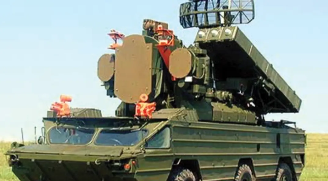
The Osa-AKM surface-to-air missile (SAM) system is deployed by the Indian Air Force and the Indian Army as an important part of their air defense inventory. Developed by the Soviet Union and having seen action in multiple wars globally, the Osa-AKM has proven to be a reliable and effective solution for countering aerial threats.

The Indian Air Force deploys the Osa-AKM SAM to protect its forward airfields. This ensures that its air assets and most importantly, the runways remain operational and free from the threat of disruption from enemy air attacks. The Indian Army, on the other hand, deploys the Osa-AKM SAM to protect its tank battalions from air attacks. So the IA’s Osa-AKM is expected to be highly mobile across multiple terrains where its tanks are deployed.

This blog looks at the Osa-AKM’s technical capabilities, operational deployment, and significance, along with the enhancements introduced by Pinaka Aerospace Solutions.

Technical Capabilities

The Osa-AKM, designated SA-8 Gecko by NATO, is a highly mobile, all-weather SAM system designed to provide tactical air defense for ground forces.

  1. Mobility:The Osa-AKM is a multi-vehicle system consisting of a combat vehicle with the missile launcher mounted on a 6×6 amphibious chassis and multiple support vehicles such as power generators, a missile check-out system, and a target acquisition and alignment system. It can achieve speeds up to 80 km/h on roads and 10 km/h in water, with a maximum range of 500 kilometers. This mobility allows for rapid deployment and repositioning, enhancing operational flexibility and survivability.
  2. Detection and Tracking:Equipped with both a target acquisition radar and a target tracking radar, the Osa-AKM can detect targets at a range of up to 45 kilometers and track them at distances of up to 30 kilometers. This dual-radar configuration supports simultaneous detection and engagement of multiple targets, providing comprehensive air defense coverage. At close ranges, it is crucial to quickly identify an incoming threat, track its path, and align the missile to neutralize it effectively. Pinaka Aerospace has contributed to the alignment system by building a new solution from the ground up for the vehicle, mast, antennas, tracker, software, and improved communication with the combat vehicle.
  3. Armament:The system carries six 9M33M3 surface-to-air missiles stored and launched from containerized canisters. These missiles can engage aircraft, helicopters, and UAVs at altitudes ranging from 25 meters to 12,000 meters and at distances up to 15 kilometers. The radio command link guidance ensures precise targeting.
  4. Electronic Counter-Countermeasures (ECCM):Advanced ECCM capabilities include frequency agility, jamming resistance, and automatic threat prioritization, ensuring the Osa-AKM remains effective in contested electromagnetic environments.

Operational Deployment

The Osa-AKM is integral to the Indian Air Force and Indian Army’s layered air defense strategy, protecting airfields, ground forces, and critical assets.

  1. Battlefield Air Defense:Primarily, the Osa-AKM provides battlefield air defense for mechanized and armored units. Its mobility enables it to advance with the troops, creating a dynamic air defense shield. The system’s effectiveness against low-flying aircraft and helicopters is crucial for countering close air support missions.
  2. Area Defense:The Osa-AKM defends command centers, logistics hubs, and airbases. Its radar and missile capabilities allow it to cover large areas and engage multiple targets simultaneously, ensuring comprehensive protection.
  3. Integration with Other Systems:Integrated into the broader air defense network, the Osa-AKM enhances situational awareness, coordination, and response times, forming a cohesive and effective defense architecture.
  4. Training and Exercises:Regular training and exercises, including live-fire drills and simulated engagements, ensure the system’s operational readiness. Joint exercises with other military branches maintain operator proficiency and system effectiveness in real-world scenarios.

Indigenization and Improvements by Pinaka Aerospace Solutions

Pinaka Aerospace Solutions has enhanced the Osa-AKM system through indigenization and technological advancements, supporting India’s self-reliance and defense modernization goals.

  1. 1. Alignment Vehicle for Osa-AKM System:Pinaka Aerospace Solutions has developed a state-of-the-art trailer-mounted Alignment System to replace the aging system supplied by the original equipment manufacturer (OEM). This indigenously developed system utilizes advanced RF technology for electronic and hydro-mechanical subsystems, ensuring long life and easy operability. Key features include:
    • State-of-the-Art RF Technology: The new system employs cutting-edge RF technology for electronic and hydro-mechanical vehicle subsystems, ensuring long life and ease of operation
    • Enhanced Operational Life: With advanced technology, the system boasts an extended operational lifespan
    • Remote Operation: The system allows remote operation of the RF system, enabling the selection of frequency, power level, and the antenna for transmission, in addition to three-axis control (Azimuth, Elevation, Tilt) of the RF Head
    • Fast Deployment and Mobility: Designed for rapid deployment with minimal manpower requirements
    • Operational Ease: Setting up the mast and other components is straightforward and efficient
    • Fully Software-Controlled: Comprehensive software control enables remote operations
    • Domestic Technology and Spares: Ensures long-term support and sustainability within India
  2. MRO of Osa-AKM Auxiliary Power Unit Gas Turbine Engine:The maintenance of Osa AK gas turbine engines, especially after the Soviet Union’s collapse became challenging due to environmental factors, operational strain, and aging parts. Pinaka stepped in to indigenize Maintenance, Repair, and Overhaul (MRO) processes for these engines. Our approach includes receiving and inspecting engines, replacing worn-out components, conducting rigorous in-house testing, and ensuring operational readiness.
    • Comprehensive MRO: Pinaka Aerospace’s MRO process involves a thorough inspection, replacement of worn-out parts, in-house testing, environmental simulation, and a systematic engine start sequence.
    • Systems Maintenance: Maintenance of engine components including compressor, combustion chamber, turbine, exhaust system, fuel system, lubrication system, ignition system, air intake, accessory gearbox, and control systems.
    • Indigenization for Operability and Savings: Indigenization offers benefits like cost efficiency, improved operational readiness, technological advancement, and autonomy to reduce reliance on former Soviet Bloc suppliers.
  3. AKIPS Missile Checkout SystemPinaka rectified challenges faced with legacy analog OEM-supplied missile checkout systems by developing the Digitized AKIPS for increased accuracy, efficiency, and manpower and equipment down-sizing.
    • Modern Software Technologies and Advanced GUI; Legacy programs were replaced with modern software technologies, better IPC, and an advanced GUI, streamlining configuration and execution processes.
    • Compact Design for Enhanced Mobility and Deployment: Pinaka’s design addresses the bulkiness and logistical challenges of legacy systems, making it easier to transport and deploy in diverse environments.
    • Simultaneous Missile Testing for Increased Efficiency: Allows simultaneous testing of two missiles, increases efficiency, and reduces time constraints.
    • Optimized Subsystem Assessments and Improved Launch Reliability: Digitized AKIPS optimizes assessments by evaluating subsystems simultaneously, saving valuable time during wartime operations and improving launch reliability.

The Osa-AKM surface-to-air missile system offers robust protection against diverse aerial threats. Its technical capabilities, operational deployment, and strategic significance are crucial in maintaining India’s defense readiness.

The indigenization and enhancements introduced by Pinaka Aerospace Solutions have bolstered the Osa-AKM’s operability. This platform is a formidable force in India’s defense arsenal with its advanced radar systems, upgraded command and control, and state-of-the-art alignment.

Pinaka Aerospace Solutions’ Compact Radar Target Simulator: Redefining Radar System Evaluation

Pinaka Aerospace Solutions has developed a state-of-the-art solution with its Compact Radar Target Simulator (CRTS). This tool enhances radar system testing, enabling the development of radars without the need for testing against live aircraft flying maneuvers. This provides for significantly reduced development time for radars since the performance of the radars can be tested frequently and for distinct lab environment characteristics. The CRTS ensures critical assets perform optimally in operational scenarios once these radars are deployed. These are some of its operational benefits and strategic importance.

Technical Overview of the Compact Radar Target Simulator

The Compact Radar Target Simulator is a cutting-edge advancement in radar system testing. Designed for precision and versatility, the CRTS is instrumental in creating realistic radar target simulations, enabling thorough assessment and refinement of radar technologies.

Key Technical Specifications:

  1. Frequency Range and Versatility: The CRTS covers an extensive frequency range, ensuring compatibility with various radar systems. This broad range facilitates the testing of echoes from different radars.
  2. Programmable Simulation: The CRTS allows the radar to be tested against multiple aircraft flying in individually programmable flight paths. This facilitates the simulation of varied blue-vs-red target scenarios for comprehensive radar system evaluation.
  3. High Precision and Resolution: The simulator offers sub-meter resolution, providing highly accurate simulations of radar returns. This level of precision is essential for evaluating radar systems’ performance in detecting and tracking targets under real-world conditions.
  4. Modular and Upgradable Design: Its modular architecture allows straightforward upgrades and customizations, adapting to evolving radar technologies and specific testing requirements. This flexibility ensures long-term utility and relevance.
  5. Integration Capabilities: Equipped with robust interfaces, the CRTS integrates effortlessly with other testing and evaluation systems. This connectivity enhances data acquisition and analysis, for a comprehensive evaluation process.
  6. Compact and Portable: Its compact design ensures ease of transport and setup in various environments, including field locations and laboratory settings. Its portability supports flexible deployment for diverse testing scenarios.

Advantages of the Compact Radar Target Simulator

The CRTS has a range of benefits that significantly enhance radar system testing and overall defense capabilities:

  1. Comprehensive Testing Capabilities: By simulating a wide array of target scenarios, the CRTS enables detailed testing of radar systems. This comprehensive approach ensures that radar systems are evaluated under multiple conditions, reflecting real-world operational environments.
  2. Realistic Simulation Environment: The CRTS generates highly realistic radar returns, providing a true-to-life simulation environment. This realism is vital for identifying and addressing potential performance issues before field deployment.
  3. Efficient and User-Friendly Operation: The simulator features an intuitive interface, simplifying configuration and operation. This user-friendly design reduces the time required for operators to become proficient and streamlines the testing process.
  4. Training and Operational Readiness: The CRTS is an effective training tool. It offers practical experience in radar system operation and data interpretation, enhancing preparedness and proficiency.
  5. Cost-Effective Testing: By enabling extensive and controlled simulations, the CRTS helps identify issues early in the development process, potentially reducing costs associated with extensive field trials and subsequent system modifications.

Operational Applications and Strategic Impact

The Compact Radar Target Simulator is used by the Indian Air Force (IAF) to maintain defense readiness and advance technological capabilities. The IAF utilizes the CRTS to test radar systems installed on aircraft and other airborne platforms. Its ability to recreate diverse target scenarios ensures that these radar systems can effectively operate in challenging environments.

The Strategic Advantage of the CRTS

The Compact Radar Target Simulator represents advancements in radar system evaluation, offering numerous strategic advantages:

  1. Enhanced Operational Readiness: By providing a platform for realistic and varied radar target simulations, the CRTS helps ensure that radar systems are thoroughly tested and ready for operational deployment, enhancing overall mission effectiveness.
  2. Support for Technological Advancements: The CRTS facilitates the integration of advanced technologies and ongoing improvements in radar systems. Its detailed testing capabilities contribute to the development of cutting-edge radar solutions.
  3. Informed Decision-Making: Accurate simulations enable better decision-making by offering insights into radar system performance. This data-driven approach supports strategic and operational decisions based on reliable information.
  4. Training and Expertise Development: The CRTS plays a crucial role in training personnel by offering hands-on experience with radar systems. This practical training is essential for developing expertise and ensuring effective operation and maintenance of advanced radar technologies.

Pinaka Aerospace Solutions’ Compact Radar Target Simulator is a modern radar system testing and evaluation solution. Its advanced technical features, realism, versatility, and cost efficiency make it an indispensable tool for defense forces. By enhancing the accuracy and reliability of radar systems, the CRTS contributes to operational readiness and technological advancement.

Indigenizing Aerospace Technology: Pinaka Aerospace’s Innovation in Fuel Flow Meter for the HAL AVRO 748

This blog explores Pinaka Aerospace’s expertise in indigenizing the fuel flow meter for the Indian Air Force’s aging AVRO, as it transitions to modern aircraft. It discusses the importance of indigenization to ensure operability, the features of the fuel flow indicator, the development process, operational efficiency, improved reliability, and self-reliance for continued national defense capabilities.

Introduction

A crucial component for aircraft operations is the fuel flow meter, which pilots use to monitor fuel consumption and ensure optimal flight performance. Pinaka Aerospace has indigenized this instrument for the AVRO aircraft, which will be phased out, giving way to the Airbus C-295.

The Need for Indigenization

Indigenization reduces dependency on foreign suppliers, particularly for obsolete systems, and ensures that the technology is tailored to meet the needs of the defense forces. The IAF uses the HAL AVRO 748 for logistics, surveillance, special missions, and training, hence the need for a reliable and precise fuel flow meter for the AVRO was critical.

Understanding the Fuel Flow Indicator

A fuel flow indicator measures the rate at which an aircraft’s power plant consumes fuel. It has a totalizer function to calculate the total fuel consumption during a flight, which can be reset to zero. This dual functionality is vital for effective monitoring and management of fuel, directly impacting the aircraft’s operational efficiency and safety.

Key Features of the Indigenized Fuel Flow Indicator

  1. Form-Fit Replacement for AVRO: The indigenized fuel flow indicator is designed as a form-fit replacement for the existing AVRO meters. This ensures direct integration without the need for extensive modifications to the aircraft.
  2. Encoder-Based Needle Positioning: Utilizing advanced encoder technology, the needle positioning is highly accurate, providing precise readings of fuel flow rates.
  3. Digital Totalizer: Including a digital totalizer enhances functionality, allowing for easy resetting and accurate tracking of total fuel consumption.

Specifications

  • Indicator Range: 0 to 2400 Lbs/hr (0.79 S.G.)
  • Totalizer Display: 4 digits in multiples of 10lb with a pushbutton to reset the totalizer to ‘0000
  • Appearance & Fitment: Identical to the existing indicator in markings and appearance, ensuring no visual discrepancies
  • Dimensions: 3.25 inch diameter x 5.12 inch length
  • Weight: Less than 1 kg
  • Qualified Standards: Compliant to MIL 461C/D and 810F/G

The Development Process

Initial Assessment and Requirement Analysis

The process began with a comprehensive assessment of the IAF’s requirements and the limitations of the existing fuel flow meters. Pinaka Aerospace conducted detailed discussions with IAF technical teams to understand the operational challenges and performance expectations. This phase defined the technical specifications and ensured that the new design meets or exceeds the performance of the existing systems.

Design and Prototyping

With a clear understanding of the requirements, our engineering team started work on the design phase. Using advanced CAD software and simulation tools, the team created detailed designs of the fuel flow indicator. The focus was on achieving high precision, reliability, and ease of integration. Prototyping was a critical step, involving multiple iterations to refine design and functionality.

Testing and Validation

Prototyping was followed by rigorous testing and validation. The prototypes were subjected to extensive lab tests to ensure compliance with MIL 461C/D and 810F/G standards, covering electromagnetic interference and environmental conditions, respectively. These tests validated the robustness and reliability of the new fuel flow meter under operational scenarios. Field testing was conducted with the IAF, where the prototypes were installed in AVRO aircraft for real-world performance evaluation. The feedback from these tests involved making final adjustments and enhancements to the design.

Implementation and Integration

Following successful validation, the final version of the fuel flow indicator was approved for production. Pinaka Aerospace ensured a smooth transition by providing detailed installation manuals and training sessions for IAF maintenance crews. The new fuel flow meters were integrated into the AVRO fleet, enhancing the aircraft’s operational continuity.

Impact and Benefits

Enhanced Operational Efficiency

The new fuel flow indicators have improved the accuracy of fuel consumption measurements, allowing the IAF to monitor fuel usage during extended missions where fuel management is critical.

Improved Reliability and Maintenance

The encoder-based needle positioning and digital totalizer reduce the likelihood of mechanical failures and inaccuracies, leading to enhanced reliability. The indigenized solution also simplifies maintenance procedures, with readily available parts and support from Pinaka Aerospace.

Strategic Self-Reliance

This indigenization effort aligns with the national vision of developing self-reliance, reducing dependency on foreign or unreliable supply chains, and enhancing indigenous capabilities, especially for assets that will be phased out.

Future Prospects

The success of the fuel flow meter project has opened new avenues for Pinaka Aerospace. It positions the company as an able partner as newer transport aircraft such as the C-295 are inducted into the air force. It also highlights Pinaka’s expertise in integrating systems into complex aircraft platforms. Pinaka has delivered cockpit instruments and engine sub-systems that are certified and proven flight-worthy. By extending our expertise to other critical components and systems in the aerospace sector, and continuously innovating and collaborating with defense forces, we aim to maintain technological leadership to support national defense objectives.

Through collaboration, design, rigorous testing, and integration, Pinaka Aerospace has delivered a solution that extends the operational capabilities of the AVRO 748. By focusing on the specific needs of the IAF and leveraging advanced engineering techniques, Pinaka Aerospace has not only met but exceeded the expectations for this critical component. Indigenizing the fuel flow meter is one example of how we lead the way in aerospace innovation.

Harnessing and Deploying Data: The Pinaka Versatile Interface Unit

Adaptability to diverse operational environments is essential in aerospace and defense, especially when integrating and utilizing data from various systems. Systems must be robust, reliable, and flexible enough to interface multiple technologies. This is particularly important for the Indian military, which has acquired a range of disparate systems over the years, adhering to various standards such as Russian, European, and NATO.

Introduction

Pinaka Aerospace Solutions addresses this challenge with the Versatile Interface Unit (VIU)—a cutting-edge solution designed to meet the demands of modern military operations. The VIU excels in capturing and utilizing data from different systems, ensuring integration and operational efficiency. This is a look at the VIU’s capabilities, technological foundations, and advantages in field operations.

Meeting the Challenge of Diverse Data Interfaces

Modern aerospace and defense operations demand systems that interface flawlessly with various technologies. Whether integrating legacy systems with new platforms or ensuring compatibility between different data standards, the ability to convert and transmit data efficiently is a critical requirement. The Versatile Interface Unit is specifically designed to address this challenge.

At its core, the VIU functions as a data interface converter, enabling the transformation of virtually any type of input into Ethernet, the most widely used network technology today. This capability allows the VIU to act as a universal adapter, bridging the gap between disparate systems and ensuring that data can be communicated effectively across all platforms.

Advanced Hardware for Unmatched Performance

The performance of the VIU is rooted in its robust hardware configuration that meets field operation requirements. Central to its design is National Instruments hardware, a trusted name in high-performance and precision instrumentation.

The VIU is housed in a MIL-Standard PXI(e) chassis, a specification that guarantees durability and reliability in operational environments. Military standards are synonymous with stringent testing and quality assurance, meaning that the VIU can withstand the rigors of operational deployments, whether in extreme climates, high-vibration conditions, or other harsh environments.

Driving the computational power of the VIU is an Intel Quad-Core i7 CPU. This processor is renowned for its balance of speed and efficiency, providing the necessary processing capability to handle complex data conversion tasks while maintaining energy efficiency. Using an i7 CPU ensures that the VIU can manage high volumes of data in real-time, a critical factor in aerospace and defense applications where decision-making speed is paramount.

Engineered for Environmental Resilience

A standout feature of the VIU is its ability to operate effectively in varying environmental conditions. Aerospace and defense operations occur in extreme environments, where temperature, humidity, and power stability pose unseen challenges and the VIU is designed to be resilient to these conditions.

The VIU operates on an input voltage range of 100-230 ± 10 Volts AC and accommodates a frequency range of 50-60 ± 2 Hz. This flexibility allows the unit to be used across global power settings, ensuring consistent performance regardless of the location.

Regarding power consumption, the VIU is efficient, drawing 10.5 Amps and consuming 700 Watts. This level of consumption is optimal for the performance it delivers, ensuring that the unit remains operational even in scenarios where power supply might be constrained. Anti-condensation heaters are another critical feature of the VIU, specifically designed to prevent moisture build-up during periods of inactivity. Condensation can be a significant issue in humid environments, potentially leading to corrosion or short circuits. Including these heaters ensures the VIU remains free from moisture-related issues, enhancing its longevity and reliability.

Moreover, these heaters are designed to automatically switch off when the main power supply is activated, further optimizing energy use and ensuring that the unit remains efficient. This feature is especially beneficial in environments where power management is crucial.

Rugged Design for Field Applications

Field operations demand equipment that is functional and exceptionally durable. The VIU excels in this regard, thanks to its ultra-rugged PXI(e) platform. This platform is engineered to withstand the physical demands of field deployments, including exposure to dust, shock, and extreme temperatures.

The VIU’s ruggedness is complemented by its built-in heaters, which allow it to operate in extremely low temperatures. This capability is critical for aerospace and defense operations conducted in polar or high-altitude environments where temperatures can plummet to levels that would disable lesser equipment.

Modular Assembly for Ease of Maintenance

A great challenge in field operations is quick and efficient maintenance. Downtime can have serious implications, potentially compromising mission success or safety. Understanding this, Pinaka Aerospace Solutions has designed the VIU with a modular assembly that simplifies maintenance and repairs.

The VIU’s modularity means that key components—such as the power supply, fan assembly, and filter tray—are easily removable. This design feature allows for rapid on-site diagnostics and the replacement of failed components without needing specialized tools or extended downtime.

This design approach enhances the unit’s reliability and reduces the total cost of ownership. By making it easier to maintain and repair, the VIU ensures continual operations with minimal disruption.

Strategic Applications and Operational Benefits

The VIU’s combination of advanced technology, rugged design, and ease of maintenance makes it an ideal solution for various strategic applications in the aerospace and defense sector.

  1. Military Operations:
    • The VIU’s data conversion capabilities enable consistent communication between different technologies, supporting integrated operations and enhancing situational awareness.
  2. Aerospace Applications:
    • It can be used to establish compatibility between legacy systems and new technologies, facilitating upgrades and extensions of operational life for existing platforms.
  3. Field Deployments:
    • The VIU’s rugged design and environmental resilience ensure that it remains operational in the most challenging conditions, whether in desert heat, polar cold, or tropical humidity.
  4. Research and Development:
    • A modular design makes it a valuable tool in research and development settings, where flexibility and ease of use are essential. Engineers can quickly reconfigure the unit to meet the specific needs of projects for faster prototyping and testing.

Why the VIU is a Game-Changer

The Pinaka Aerospace Solutions Versatile Interface Unit’s ability to convert any data interface into Ethernet, combined with its robust hardware, environmental resilience, and modular design, sets it apart from other solutions on the market.

The VIU offers a powerful tool that enhances operational capability, reduces maintenance downtime, and ensures compatibility across different technologies. Its value is reinforced by its adaptability, from front-line military operations to cutting-edge research and development.

As the aerospace and defense industries evolve, the need for versatile, reliable, high-performance equipment increases exponentially. The Pinaka Aerospace Solutions Versatile Interface Unit is at the forefront of meeting this need. By providing a robust, adaptable, and easy-to-maintain solution, the VIU meets the current demands of the industry and positions itself as a vital component in the future of aerospace and defense technology. For organizations looking to enhance their operational effectiveness and ensure seamless data integration across multiple platforms, the VIU is an asset designed to meet future challenges.

ZETWERK-Pinaka’s Expertise in Avionics Integration

Integrating the Hand Control Panel (HCP) with the joystick in DARIN-compatible Jaguar aircraft is a consequential advancement in cockpit operations and operability extension. The ZETWERK-Pinaka solution augments pilot control, situational awareness, and operational efficiency in DARIN II and DARIN III systems. The result is a future-proofed solution that delivers performance in combat situations and mission success.

Introduction

The success of any sortie hinges on the interaction between pilots and aircraft avionics systems. One such advancement is the integration of the Hand Control Panel (HCP) with the joystick in DARIN-compatible Jaguar aircraft for pilot control and streamlined cockpit operations.

Revolutionizing Cockpit Interfaces

The cockpit is the command center of any aircraft, where pilots manage multiple systems—from navigation and communication to weapons control and avionics management. Over the decades, cockpit interfaces have advanced from traditional switches and knobs to sophisticated digital panels and multifunction displays (MFDs). The challenge lies in integrating these systems to optimize performance for ease of pilot use.

Facilitating the Integration: ZETWERK-Pinaka’s Role

ZETWERK-Pinaka facilitated this integration through close interaction with the DPSU and testing pilots.

  1. Comprehensive System Analysis: ZETWERK-Pinaka initiated the process by analyzing the existing avionics architecture and the specific requirements of the DARIN II and DARIN III systems. This analysis identified the challenges and requirements for successful integration.
  2. Hardware Optimization: To ensure flawless interaction between the HCP and joystick, we engineered a hardware solution that aligned physical components, optimized electrical interfaces, and redesigned control mechanisms. This hardware integration was crucial for achieving the desired operational fluidity within the cockpit.
  3. Advanced Software Integration: ZETWERK-Pinaka developed sophisticated software protocols that facilitated real-time data exchange and communication between the HCP, joystick, and DARIN systems. Software integration synchronized functionality, flight control management, and avionics systems through a unified interface.
  4. Human Factors Engineering: Recognizing the importance of pilot interaction with cockpit systems, we incorporated human factors engineering into the integration. The HCP and joystick have been designed and ergonomically engineered, featuring intuitive layouts and tactile feedback mechanisms for ease of use, efficiency, and decision-making capabilities.
  5. Rigorous Testing and Validation: The integrated HCP and joystick system underwent extensive testing, including hardware-in-the-loop simulations, flight tests, and stress testing. Rigorous validation protocols ensured the system met all required performance, safety, and compatibility standards under various operational conditions.
  6. Customization for Mission-Specific Needs: Understanding the operational demands of the Jaguar aircraft, ZETWERK-Pinaka customized the integration to align with specific mission profiles. This customization included configuring the HCP and joystick to manage navigation modes, weapons selection, and targeting systems in a manner that supports tactical objectives.
  7. Ensuring Future Compatibility: ZETWERK-Pinaka focused on future-proofing the integration by designing the system to accommodate future avionics upgrades. This approach ensures that the Jaguar aircraft remains operable and compatible with emerging technologies and can easily incorporate new sensors, mission systems, and avionics enhancements as they become available.

Why is it Important to Integrate the HCP and Joystick

The Hand Control Panel (HCP) is essential for pilots to manage avionics, select weapons, and control navigation modes. The joystick controls flight, including pitch, roll, and yaw movements. Integrating these two critical interfaces into a cohesive system is vital for creating a unified cockpit experience that reduces cognitive workload and enhances operational efficiency.

Ensuring DARIN Compatibility: A Complex Integration of HCP and Joystick Systems

The DARIN (Display Attack Ranging Inertial Navigation) system is a series of avionics upgrades designed to modernize aircraft operational capabilities. Ensuring the HCP and joystick are fully compatible with DARIN II and DARIN III standards is a complex task that requires hardware integration, software interfacing, and human factors engineering. This integration is crucial for pilot safety, aircraft survivability, and mission success.

Conclusion: Commitment to Avionics Excellence

ZETWERK-Pinaka’s role in integrating the Hand Control Panel (HCP) with the joystick in Jaguar aircraft using cutting-edge expertise in hardware optimization, software integration, and human factors engineering has enhanced efficiency, ensured future compatibility, and contributed to mission success in operational environments.

Indigenizing the MRO of Osa AK Gas Turbine Engines: A Triumph by Pinaka Aerospace Solutions, a ZETWERK Company

In the 1980s, India bolstered its air defense capabilities by acquiring the 9K33 Osa surface-to-air missile systems from the Soviet Union. These systems, known for their agility and effectiveness in low-altitude, short-range air defense, have served the Indian Armed Forces with distinction for decades. Among the variants procured were the 9K33 Osa, 9K33M2 Osa-AK, and 9K33M3 Osa-AKM, each bringing progressive enhancements in radar and missile technology.

Powering these mobile missile platforms is the Osa AK gas turbine engine, its auxiliary power unit, and a critical component responsible for powering missile launch operations. However, with the dissolution of the Soviet Union and the subsequent challenges in maintaining these engines, the Indian Armed Forces faced increasing difficulties. Pinaka Aerospace Solutions, a ZETWERK company, has indigenized the Maintenance, Repair, and Overhaul (MRO) processes for these engines, ensuring sustained operational efficiency and strategic autonomy for India.

The Challenges of Maintaining Osa AK Engines

The Osa AK gas turbine engine has encountered multiple challenges over the years. These issues stemmed from:

  1. Environmental Factors: India’s diverse climate, ranging from hot deserts to humid coastal regions and high-altitude cold areas, subjected the engines to significant wear and tear. This affected their reliability and efficiency, necessitating frequent and specialized maintenance.
  2. Maintenance and Spare Parts: Post-USSR collapse, acquiring spare parts became a daunting task. The lack of a steady supply chain led to delays in maintenance and suboptimal performance.
  3. Operational Strain: The high operational demands placed on these missile systems, often used without adequate downtime, accelerated wear and tear, especially in active conflict zones and military exercises.
  4. Aging Systems: Over time, metal fatigue, corrosion, and other age-related issues began to compromise the engines’ functionality.

Pinaka Aerospace Solutions: Addressing the MRO Challenges

Pinaka Aerospace Solutions aimed not only to overcome these challenges but also to establish a sustainable, self-reliant ecosystem for these weapons platforms.

Key Components of the Osa AK Gas Turbine Engine

The Osa AK gas turbine engine is composed of several critical components, each requiring maintenance and sometimes, complete overhaul:

  • Compressor: Includes compressor blades and stator vanes, essential for compressing incoming air and increasing pressure.
  • Combustion Chamber: Houses fuel injectors and spark plugs for mixing fuel with compressed air and igniting the mixture.
  • Turbine: Comprises turbine blades and discs, which extract energy from high-temperature gasses to drive the compressor and produce thrust.
  • Exhaust System: Contains the exhaust nozzle, directing the flow of gasses to convert energy into thrust.
  • Fuel System: Features fuel pumps and a fuel control unit to regulate fuel flow.
  • Lubrication System: Includes oil pumps and filters to reduce friction and protect components.
  • Ignition System: Comprises the ignition exciter, providing high-voltage pulses to spark plugs.
  • Air Intake: Utilizes inlet guide vanes to optimize airflow.
  • Accessory Gearbox: Drives various accessories like fuel and oil pumps.
  • Control Systems: Managed by the Engine Control Unit (ECU), optimizing performance and efficiency.

The MRO Process by Pinaka Aerospace Solutions

Pinaka Aerospace Solutions’ approach to MRO involves a comprehensive and systematic process to ensure the Osa AK engines are maintained at peak efficiency. A customer’s representative is always present during the entire process, ensuring transparency and adherence to standards. The process encompasses several critical stages:

  1. Receiving and Initial Inspection:
    • Receiving the Engine: The engine is carefully received and logged into the system.
    • Visual Inspection: A thorough visual inspection is conducted to identify any obvious signs of damage or wear.
  2. Component Assessment and Replacement:
    • Discarding Worn-Out Parts: Identified worn-out or damaged parts are discarded.
    • Substituting with Compatible Alternatives: Compatible alternatives for components such as gaskets, rings, and bearings are sourced and installed.
    • Rebuilding Gear Cogs: Gear cogs are rebuilt to ensure seamless operation.
  3. In-House Testing and Simulation:
    • Testing Facility: The engine undergoes rigorous testing in an in-house testing facility. All critical operation parameters are measured in long-duration tests and verified to be performing satisfactorily.
    • Environmental and Operational Simulation: Tests simulate various environmental and operational conditions to verify the engine’s reliability and performance in varying conditions.
  4. Pre-Start Checks:
    • Verify fuel supply and clear fuel lines.
    • Ensure oil levels and electrical systems are operational.
    • Inspect air intake for obstructions.
  5. Power On:
    • Activate main power and ignition systems.
  6. Engine Start Sequence:
    • Engage the starter motor to rotate the compressor and turbine.
    • Ignite the fuel-air mixture in the combustion chamber.
    • Monitor engine parameters as it accelerates.
  7. Stabilize at Idle:
    • Maintain idle speed and ensure all parameters are within limits.
    • Check for oil pressure stability and the absence of leaks.
  8. Operational Readiness:
    • Perform final checks, ensuring cooling systems and exhaust are clear.
    • Engage additional systems powered by the engine if applicable.
  9. Transition to Full Power:
    • Gradually increase throttle while monitoring parameters to avoid overheating or overpressure conditions.

Throughout the MRO process, constant monitoring and adherence to safety protocols are crucial to prevent malfunctions and ensure the engines’ longevity.

Indigenization: A Strategic Imperative

Indigenizing the MRO of the Osa AK gas turbine engines is a strategic imperative for India. By achieving self-reliance in maintaining these engines, Pinaka Aerospace Solutions has mitigated the risks associated with dependency on foreign suppliers.

Key Benefits of Indigenization

  • Cost Efficiency: Reducing reliance on foreign parts and expertise lowers maintenance costs and improves the cost-efficiency of the defense budget.
  • Operational Readiness: Ensuring a steady supply of spare parts and timely maintenance enhances the operational readiness of missile systems.
  • Technological Advancement: Developing indigenous capabilities fosters technological advancement and innovation within the country.
  • Strategic Autonomy: Reducing dependency on foreign suppliers strengthens India’s strategic autonomy and national security.

The Role of ZETWERK in Empowering Pinaka Aerospace Solutions

As a part of ZETWERK, Pinaka Aerospace Solutions benefits from access to cutting-edge manufacturing technologies and a vast network of suppliers. ZETWERK’s expertise in precision engineering, supply chain management, and industrial automation significantly augments Pinaka’s capabilities.

Technological Integration and Innovation

  • Advanced Manufacturing: Leveraging ZETWERK’s advanced manufacturing techniques ensures high-quality production of critical engine components.
  • Supply Chain Resilience: An extensive and resilient supply chain network guarantees the availability of spare parts and reduces lead times.
  • Innovation and R&D: Continuous investment in research and development drives innovation, leading to the development of more efficient and durable components.

The indigenization of the MRO processes and several frequently-failing components of the Osa AK gas turbine engines by Pinaka Aerospace Solutions marks a significant milestone in India’s defense capabilities. This initiative addresses the longstanding challenges faced by the Indian Armed Forces and establishes a framework for future self-reliance in defense technology.

By integrating advanced manufacturing techniques, ensuring supply chain resilience, and fostering innovation, Pinaka Aerospace Solutions has highlighted the importance of strategic autonomy and showcases the potential of Indian enterprises to rise to the occasion and meet critical national defense needs.

The Pinaka R73 Pre-Load Plug Tester: A Leap Forward in Indigenous Defense Technology

Among the critical systems ensuring the operational effectiveness of modern air combat assets are air-to-air missiles. AAMs are both mission-critical and safety-critical in achieving objectives during war. Reliable and trustworthy pre-load testing of AAMs onto fighter aircraft is an essential part of operational deployment. A Pre-Load Tester is needed to guarantee that munitions are fully functional and safe before they are mounted on aircraft. The Indigenous development of the R73 Pre-Load Plug Tester by Pinaka Aerospace Solutions, a ZETWERK company is a milestone for defense technology.

Overview of the R73 Missile

Before we look at the Pinaka R73 Pre-Load Tester, it’s essential to understand the missile it supports. The R73 missile, known by its NATO reporting name AA-11 Archer, is a highly capable short-range air-to-air missile developed by the Soviet Union. Known for its agility, accuracy, and effectiveness in close-range combat, it has been a staple in aerial warfare since the 1980s. The R73 features a high off-boresight capability, advanced infrared guidance, and thrust vectoring control, making it a formidable dogfight weapon.

Understanding the Significance of Pre-Load Plugs

Pre-load plugs are electrical connectors to establish connections between aircraft systems and mounted weapons, such as missiles or bombs. These plugs transmit power, signals, and data, enabling the aircraft to control and deploy its armaments, and it is imperative to verify the functionality and integrity of pre-load plugs through rigorous testing.

The Genesis of Pinaka’s Innovation

Pinaka has designed and delivered a reliable and versatile pre-load plug tester tailored to the specifications of the R73 missile with a deep understanding of weapons technology.

Key Features of the R73 Pre-Load Plug Tester

  1. Comprehensive Connectivity Testing:
    • The R73 Pre-Load Plug Tester performs thorough continuity checks, ensuring that electrical connections between the aircraft and R73 missiles are secure, reliable, and functional.
    • It verifies compatibility with various pre-load plug configurations, accommodating different aircraft platforms seamlessly.
  2. Advanced Diagnostic Capabilities:
    • Using state-of-the-art diagnostics, the tester identifies and troubleshoots electrical faults, ensuring optimal performance and safety.
    • Maintenance personnel benefit from quick and accurate fault detection, reducing downtime and enhancing operational readiness.
  3. Safety Assurance:
    • The tester includes safety checks to prevent short circuits, electrical overloads, and other potential hazards during weapon deployment.
    • It adheres to stringent safety standards, contributing to the overall safety of aircraft operations.
  4. User-Friendly Interface:
    • Designed for ease of use, the R73 Pre-Load Plug Tester features an intuitive interface that streamlines testing procedures.
    • Maintenance personnel can navigate through tests, interpret results, and generate reports efficiently, enhancing workflow efficiency.

Impact on Operational Readiness and Cost Efficiency

The deployment of Pinaka’s R73 Pre-Load Plug Tester has significant implications for both operational readiness and cost efficiency within the defense sector:

  1. Enhanced Reliability:
    • By ensuring the functionality and integrity of pre-load plugs, the tester enhances the overall reliability of aircraft weapon systems.
    • This reliability is crucial in mission-critical scenarios, where swift and accurate weapon deployment is essential.
  2. Reduced Downtime:
    • The advanced diagnostic capabilities of the tester minimize troubleshooting time, leading to reduced downtime for maintenance and repairs.
    • This reduction in downtime translates to increased aircraft availability and operational continuity.
  3. Cost Savings:
    • Pinaka’s indigenous innovation translates to cost savings for defense establishments, reducing dependency on expensive imported testing equipment.
    • The lifecycle cost of maintaining aircraft weaponry is optimized, contributing to overall budgetary efficiency.

Technological Advancement and Strategic Autonomy

The development and deployment of the R73 Pre-Load Plug Tester underscore India’s technological prowess and commitment to strategic autonomy in defense:

  1. Technological Sovereignty:
    • Pinaka’s indigenous innovation represents a step towards technological sovereignty, reducing reliance on external suppliers and fostering self-reliance.
    • It strengthens India’s defense ecosystem by nurturing domestic expertise and capabilities in advanced testing technologies.
  2. Innovation Ecosystem:
    • The success of the R73 Pre-Load Plug Tester catalyzes further innovation and collaboration within India’s defense industry.
    • It encourages synergies between defense establishments, research institutions, and private sector entities, fostering a robust innovation ecosystem.
  3. Global Recognition:
    • The R73 missile is widely deployed by many countries worldwide for use on a variety of fighter aircraft. With the Pre-Load Tester, Pinaka has opened up a very wide market. Even better, several other missiles have the same or very similar characteristics as the R73, and Pinaka has designed the tester intending to be easily deployed for all missiles of this class.
    • Pinaka’s prowess in developing indigenous defense solutions garners global recognition, positioning India as a competitive player in the international defense market.
    • The R73 Pre-Load Plug Tester exemplifies India’s ability to develop cutting-edge technologies that meet global standards of quality and performance.

Future Prospects and Collaborations

Looking ahead, Pinaka Defense Systems envisions a roadmap of continued innovation and collaboration:

  1. Expansion of Testing Capabilities:
    • The success of the R73 Pre-Load Plug Tester paves the way for developing testers for other weapon systems, further enhancing testing capabilities across the spectrum.
    • This expansion contributes to comprehensive testing solutions for diverse defense applications.
  2. International Partnerships:
    • Pinaka’s indigenous innovations open avenues for international collaborations and partnerships, facilitating technology transfer and knowledge exchange.
    • Collaborative ventures strengthen global defense capabilities and foster diplomatic ties.
  3. Innovation Driven by User Feedback:
    • Pinaka remains committed to continuous improvement, incorporating user feedback and evolving technological advancements into future iterations of testing equipment.
    • User-centric design and functionality enhancements drive ongoing innovation efforts.

Pinaka Defense Systems’ development of the R73 Pre-Load Plug Tester marks a significant milestone in India’s journey towards technological self-reliance and defense innovation. This indigenous solution embodies excellence in engineering, reliability in testing, and a steadfast commitment to national security. As Pinaka continues to push boundaries and forge new frontiers in defense technology, the R73 Pre-Load Plug Tester stands as a testament to India’s capabilities on the global stage.